
Selecting an Engineered Foundation Design Type
The American Society of Civil Engineers Texas chapter put together a recommended practice that serves as the ‘gold standard’ for selecting the appropriate foundation on expansive soils in Texas. The document is titled “Recommended Practice for the Design of Residential Foundations”. Two of the approved options will be discussed since they are the most common: conventionally reinforced and post tensioned.
Conventionally Reinforced Engineered Slab Design
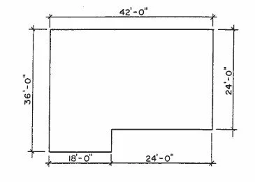
Step 1:
The general floor plan layout is established. A simple example is shown.
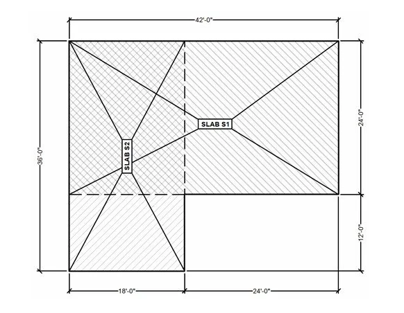
Step 2:
The floor plan is divided into overlapping rectangles to allow the evaluation of each rectangle as if it were it’s own foundation.
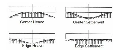
Step 3:
Different types of soil movement are taken into account which can occur in expansive soils.
Step 4:
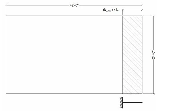
The appropriate length of foundation soil support to neglect is calculated through engineering methodology. My designs consider no less than 6 feet of soil to be missing in both directions (this is a recognized engineered slab design best practice). One figure shows shows the short side of slab S1 with no support and the other figure shows the long side of slab S1 with no support (hatched areas).

Step 5:
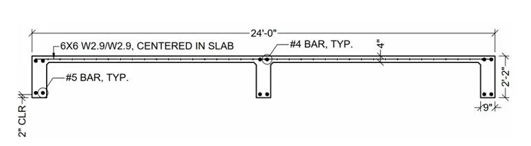
Through detailed engineering calculations considering no soil support under part of the slab, the required concrete beam dimensions & steel reinforcement requirements are calculated. These results withstand the stresses with additional safety factor. The adjacent slab section view demonstrations the required dimensions and steel reinforcement required for the long-span direction of the slab.
Step 6:
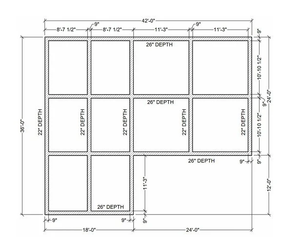
After many additional steps of engineering calculations are performed, the final layout of the slab is determined.
General comments on conventionally reinforced concrete slabs:
All concrete will crack due to shrinkage — this is normal and typically acceptable. Cracks do not necessarily indicate foundation issues or failure. The purpose of reinforcement is to restrain the crack size and provide additional tensile strength to the concrete. Most observable concrete cracking due to shrinkage should be limited to hairline cracks. If there are design features such as sealed concrete where the slab is exposed, discussion should be had regarding whether or not hairline cracks are visually acceptable.
Typically, when looking at a conventionally reinforced slab drawing there should be a reasonable pattern of foundation beams creating squares or rectangles. If the foundation is made of several irregular or a non-repetitive pattern of squares/rectangles it is likely not an optimal design. The drawing should look relatively simple and repetitive like the final slab design shown above. An exception would be beam placement at heavily loaded interior walls; however, details like this can typically be accommodated with a repetitive pattern as discussed previously.
Beam spacing can vary, but anything above a 15 foot spacing should be carefully investigated. In reality, beams should be spaced closer together than 15’.
It is critically important to perform soil tests when designing a foundation. When soil tests are skipped, the owner will have no reliable data showing their foundation will perform well long term. If a design/build company recommends a soil test it is a good sign you are working with a competent constructor.
Design methodology and figures used on this page are from the Wire Reinforcing Institute’s (WRI) RF-700 "Design of Slab on Ground Foundations” Tech FactPost Tensioned Engineered Slab Design
Step 1:
The general floor plan layout is established. A simple example is shown.
Step 2:
The floor plan is divided into overlapping rectangles to allow the evaluation of each rectangle as if it were it’s own foundation. While it seems similar to the conventionally reinforced foundation design methodology, there is an additional step of evaluating the total slab “shape factor”. Essentially, the shape factor ensures the slab shape is not irregularly shaped preventing a post tensioned slab from being totally effective.
Step 3:
Specific foundation parameters are determined such as the perimeter load (exterior walls) and uniform load to be applied to the slab. Specific geotechnical parameters are required to determine soil movement characteristics. A geotechnical report is absolutely required for a post tensioned slab.

Step 4:
A foundation grid is determined for the initial design. It is best practice to ensure all interior beams are continuous to the perimeter beams. An example grid layout is shown for slab S1.

Step 5:
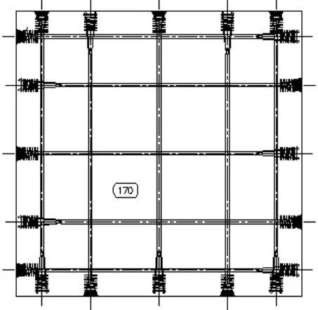
Slab tendons are specified at particular spacing to provide adequate compression across the slab. Effectively, the tendons “squeeze” the slab together. This action provides resistance to slab damage due to soil activity. A simplified figure is shown demonstrating a typical layout pattern of tendons. Tendons should be spaced between 3’ - 4’ in residential slab on grade foundations. Additional tendons are provided in all of the beams. The beam tendons are laid in a “draped” fashion and when tightened, the tendons create a vertical force in the center of the beams. This force helps prevent deflection under load or lack of beam support (soil movement). Traditional reinforcement may also be specified in certain areas of the slab.

General comments on post tensioned slabs:
All concrete will crack due to shrinkage — this is normal and typically acceptable. Cracks do not necessarily indicate foundation issues or failure. Concrete shrinkage cracking can occur between the time of slab pouring and tensioning of the tendons. Tendons should be tensioned within approximately 5-10 days after pouring the slab. Strength of the concrete should also be evaluated if tensioning the tendons early. It can be the case that tensioning the slab can ‘close’ shrinkage cracks. This may not always be the case and the best chances of success are if the tendons are tensioned as early as possible (concrete gets substantially stronger day over day until specified maturity).
Post tensioned slabs account for a large portion of new residential slabs being built in Texas. This is due to the historical superior performance in expansive soils and the ability to restrain cracking.
Beam spacing can vary, but it is typical to see beam spacing between 8-12 feet.
It is critically important to perform soil tests when designing a post tensioned foundation. Additionally, a structural engineer does not have enough information to properly design a post tensioned slab due to certain input parameters that must be gathered from a geotechnical report.
Design methodology presented is from PTI DC10.5-19: Standard Requirements for Design and Analysis of Shallow Post-Tensioned Concrete Foundations on Expansive and Stable Soils